
LeoCentaur's Theremin Page

I would like to thank Art at Art's Theremin Page (his new link is www.theremin.us) and the people at http://www.ax84.com/ (The Cooperative Tube Guitar Amp Project) for their help in making this project possible.
A couple of other links that may be useful:
http://www.electrotheremin.com/megalink.html
http://www.zzounds.com/edu--thecultofthetheremin
My theremin was built using the design
of the 126 theremin from Art's Theremin Page; I made some modifications to the 126 design
to use parts that I had on hand. This is my second theremin and my first vacuum tube
project. The capacitors and resistors were purchased new, however, the coils were
hand wound on slug-tunable coil forms, the ceramic resonator was scavenged from an old
remote control unit (it took a few tries to find the correct load capacitors for the
resonator), the variable air capacitors as well as the gears to fabricate the capacitor
tuning units were scavenged from old electronics equipment.
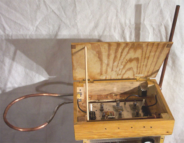
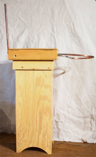
I used the rod and loop antennae, not for any practical purpose but,
because the first theremin I saw was a photo of Leon Theremin's original instrument and
that's how I wanted my theremin to look. The size of the antennae approximate the
surface area of the 8" x 5-1/2" plates called for in the design specs. The
pitch antenna is a piece of galvanized steel electrical pipe (conduit), 3/4" external
diameter and approximately 19" long (18.6742" to be precise). The volume
antenna was a piece of aluminum pipe 1/2" with the inside diameter of the loop
being 9" (I tried to get the loop diameter down to 8", but it was just too much
work). After I got my theremin working, I electroplated the pitch rod with copper
and replaced the aluminum volume antenna with a copper one.
I used 1 watt resistors instead of the 1/2 watt in case I did some tweaking
that might overload the 1/2 watt resistors. I made a number of changes to the power
supply. The power supply uses Radio Shack transformers. One transformer is for
the filament heaters. I have two 25 Volt (0.45A) transformers hooked in series (and
in-phase) for the theremin circuit. I added a small choke coil, an
additional 330uF capacitor and a 56K 2-watt bleeder resistor to the power supply.
All this, of course, raising the supply voltage from the recommended 50 volts to about 72
volts.
For those of you who are interested, you can download a program, written in QuickBasic, for coil design. The download file is a text based version of the program that should be adaptable to other versions of BASIC.
I got this program out of an old electronics magazine. It is a combination of several different programs; I didn't want to wade through a bunch of programs to find the coil design program. If you are well versed in BASIC, you may find the program useful; otherwise, you may find it quite confusing. It's best for designing small coils 0.001 to 2.0 milli-Henries (1 to 2,000 uH). |
|
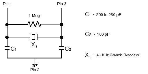 This is the schematic for the ceramic resonator that I substituted for the one called for in the theremin 126 design. This is by no means definitive; all I know is that it works in my theremin. Perhaps, someone else with more qualifications than myself could refine it. |
![]()
I built this device to hand wind coils.
![]()
Click on photos to see a larger image
Download mp3 sound sample. The file is 385kb in size, encoded at 96kbs, mono, 44.1kHz and is 31 seconds long.
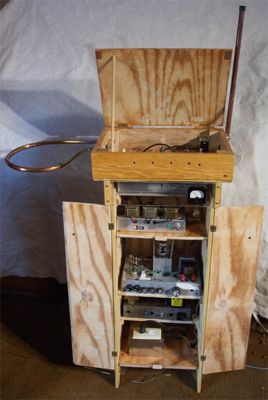
The vacuum tube amplifier for my theremin was built using the schematic for the Hi-Octane model (Revision 05.11.23). Thanks, again, to the people at http://www.ax84.com/. As with the theremin, most of the parts were scavenged from old electronics equipment. I bought new caps, pots, resistors and some mounting hardware. I had some 1625 vacuum tubes (RCA VT-136) which were ideal for the output stage of the amplifier. The power supply and the amp were built as separate units. I drew up my own parts layout diagrams to accommodate my modifications. I put a choke coil in the power supply just because I had some on hand.
![]()
![]()
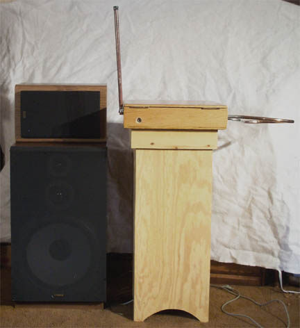
Frankentheremin lives!
I have approximately 290 tubes (about 130 different tube numbers) in my collection. I have a few interesting tubes and several that I haven't been able to identify. If you are interested, download the list. If you want a photo of any of the tubes, e-mail me (e-mail address is at the bottom of this page); I already have some photos of the tubes that I think are the most interesting.

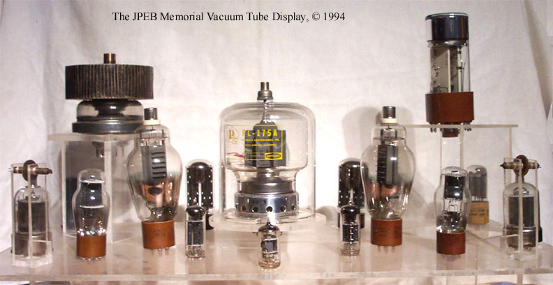
The "John P. Billey Memorial Vacuum Tube Display"
Download the Tiranti Font:

If you are interested in any of the details about the construction of my theremin, send e-mail inquiries to Chris at:
![]()
Because of the enormous increase in junk e-mail, I converted my e-mail address to a jpg file in order to thwart bots that scan for text e-mail addresses. No hyper-link or copy and paste; sorry for this inconvenience.
Powered by WebRingÛ.
|
LeoCentaur's Fractal Antennae for DTV reception - https://leocentaur.angelfire.com/dtva.html
A Satirical Take on The Revolutionary Switch to Digital Television - https://leocentaur.angelfire.com/dtv1.html
E-books: The Memoirs of John F. Doe - https://leocentaur.angelfire.com/alitw.html
Stand-Alone File Sort Utility for Windows 95/98/ME/2000/XP - https://leocentaur.angelfire.com/wrqsort.html